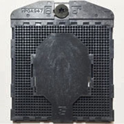
- Programmer socket
- Bios Chip Programming
- Programmer & Sockets
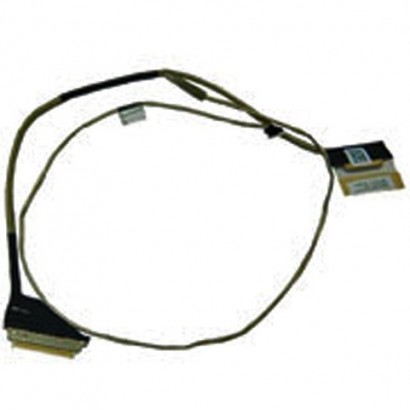
- EFI Rom Cable
- Zip Clip Holder
- Ebay Store Chipsetpro
- Pin Holder
- Data Recovery Tool
- Limited-Time Offer
- Bundles and Sets
- Pre-Order
- Programmer
- CPU and Graphic Chips
- Laptop Parts, Repair tool
- Adapter, DC cable
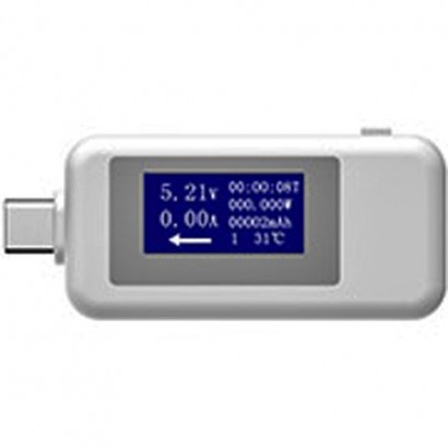
- Multimeter, Test Tools
- Apple Parts, BIOS EMC,...
- Other BGA Chips & ICs
- DC Jacks, Connector
- BGA Reballing Kits,...
- PCI, CPU Socket Tester
- Car Service Equipment
- Laptop used parts,...
- Programmer Spare Part
- BGA Soldering...
- Membership plan
Active filters
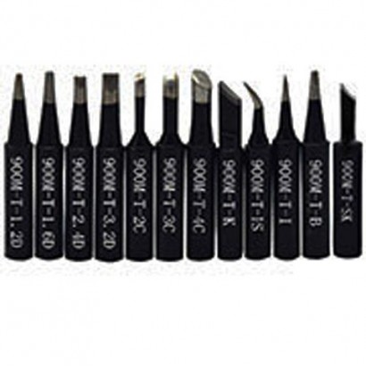
900MT24D KINGBOX 936 leadfree soldering iron head thermostatic head
€3.61
900M-T-2.4D KINGBOX 936 lead-free soldering iron head thermostatic head
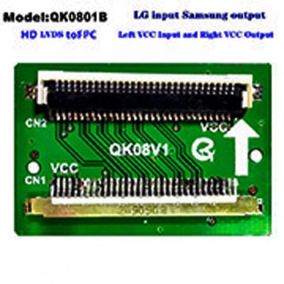
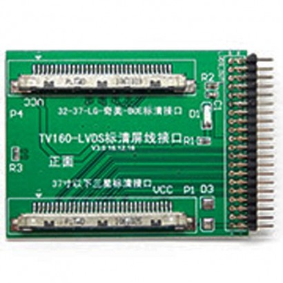
TV160 LVDS BOE Conversion Link Board for LG CHIMEI 3237Samsung 37Below
€9.82
TV160 LVDS BOE Conversion Link Board for LG CHIMEI 32-37Samsung 37Below
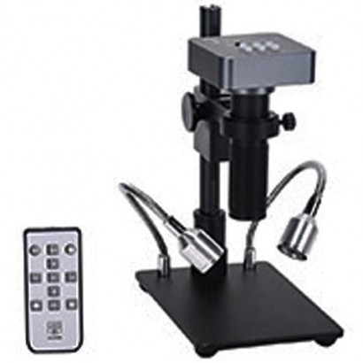
HDMI USB1080P 48mp Digital Electronic Video Microscope Camera 120X Cmount Lens Phone PCB Soldering Repair Industrial Work Set
€180.26
HDMI USB1080P 48mp Digital Electronic Video Microscope Camera 120X C-mount Lens Phone PCB Soldering Repair Industrial Work Set
TV18 Test Tool LED LCD Screen Tester Support 784Voltage Transformer Board 14 LVDS
€55.82
T-V18 Test Tool LED LCD Screen Tester Support 7-84+Voltage Transformer Board 14 LVDS
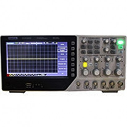
Hantek DSO4204C Digital Oscilloscope 200MHz 4Channels Bandwidth 1GSas Waveform Generator
€468.69
Hantek DSO4204C Digital Oscilloscope 200MHz 4Channels Bandwidth 1GSa/s Waveform Generator
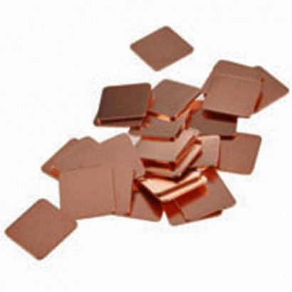
12 15mm15mm Heatsink Thermal Pad Copper Shim for Laptop CPU GPU Copper Plate
€2.70
1.2 15mm*15mm Heatsink Thermal Pad Copper Shim for Laptop CPU GPU Copper Plate
900MT24D KINGBOX 936 leadfree soldering iron head thermostatic head
€3.61
900M-T-2.4D KINGBOX 936 lead-free soldering iron head thermostatic head
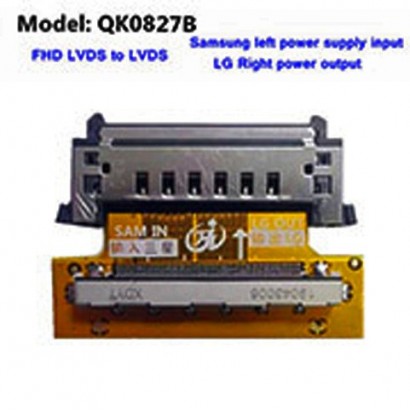
TV160 LVDS BOE Conversion Link Board for LG CHIMEI 3237Samsung 37Below
€9.82
TV160 LVDS BOE Conversion Link Board for LG CHIMEI 32-37Samsung 37Below
HDMI USB1080P 48mp Digital Electronic Video Microscope Camera 120X Cmount Lens Phone PCB Soldering Repair Industrial Work Set
€180.26
HDMI USB1080P 48mp Digital Electronic Video Microscope Camera 120X C-mount Lens Phone PCB Soldering Repair Industrial Work Set

TV18 Test Tool LED LCD Screen Tester Support 784Voltage Transformer Board 14 LVDS
€55.82
T-V18 Test Tool LED LCD Screen Tester Support 7-84+Voltage Transformer Board 14 LVDS
Hantek DSO4204C Digital Oscilloscope 200MHz 4Channels Bandwidth 1GSas Waveform Generator
€468.69
Hantek DSO4204C Digital Oscilloscope 200MHz 4Channels Bandwidth 1GSa/s Waveform Generator
12 15mm15mm Heatsink Thermal Pad Copper Shim for Laptop CPU GPU Copper Plate
€2.70
1.2 15mm*15mm Heatsink Thermal Pad Copper Shim for Laptop CPU GPU Copper Plate