DC Cable Adapter 7450 to 4530 for DELL HP Power Charger Converter
€4.35
DC Cable Adapter 7.4*5.0 to 4.5*3.0 for DELL HP Power Charger Converter
Active filters
DC Cable Adapter 7.4*5.0 to 4.5*3.0 for DELL HP Power Charger Converter
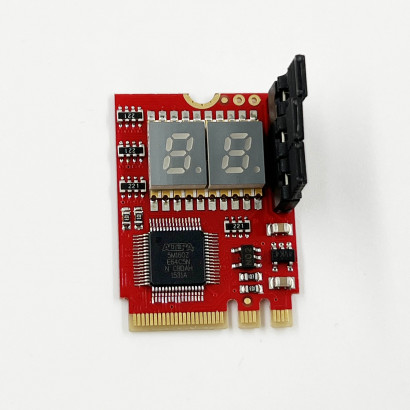
TL631-Pro Diagnosis Card + MINI PCIE + A-DEBUG Desktop PCI Mainboard PCI-e Notebook Debugging Card Apple PC LPC Debug
1 set DC Power 5.5*2.1mm Jack to 40 Plug Adapter Notebook Universal Adapter Connector + DC Cable AC adapter
1 set DC Power 5.5*2.1mm Jack to 8 Plug Adapter Notebook + SAMSUNG HP Connector
Laptop Notebook 1150 Dummy Loading Board Test Card CPU Socket Tester
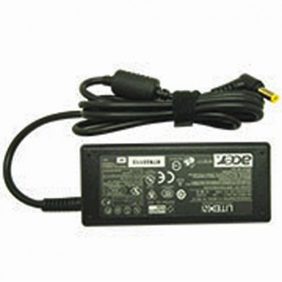
ASUS Car charger for notebook 19V 3.42A 65W 5.5*2.5mm
3in1 Mini PCI-E PCI LPC 2 Digit PC Analyzer Combo-Debug-Card repair tool
Universal Multi-function POST Card LPC + Compal NGFF for diagnostics and testing

DC Cable Adapter 7.4*5.0 to 4.5*3.0 for DELL HP Power Charger Converter

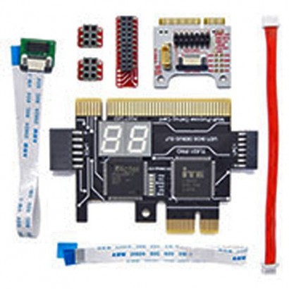
TL631-Pro Diagnosis Card + MINI PCIE + A-DEBUG Desktop PCI Mainboard PCI-e Notebook Debugging Card Apple PC LPC Debug

1 set DC Power 5.5*2.1mm Jack to 40 Plug Adapter Notebook Universal Adapter Connector + DC Cable AC adapter


1 set DC Power 5.5*2.1mm Jack to 8 Plug Adapter Notebook + SAMSUNG HP Connector
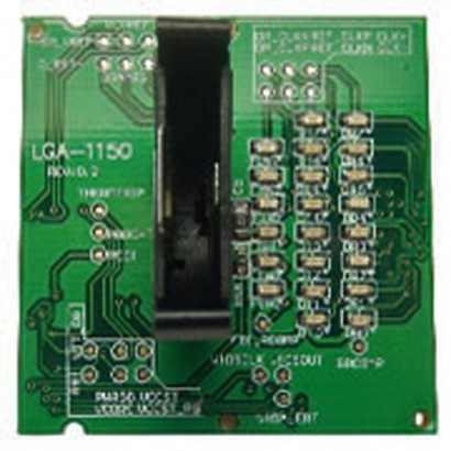
Laptop Notebook 1150 Dummy Loading Board Test Card CPU Socket Tester
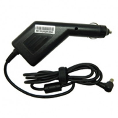
ASUS Car charger for notebook 19V 3.42A 65W 5.5*2.5mm
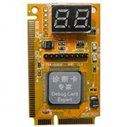
3in1 Mini PCI-E PCI LPC 2 Digit PC Analyzer Combo-Debug-Card repair tool
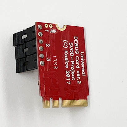
Universal Multi-function POST Card LPC + Compal NGFF for diagnostics and testing